Overview
The transcoding functionalities of Silverstack have been updated with Silverstack Lab 6. The update contains a faster transcoding engine, an updated user interface, more transcoding options and a lot more (details below).
Individual Clip vs Combined Clips Transcoding
Silverstack Lab offers two different basic transcoding options:
![Fig. 0: The two main transcoding options in Silverstack Lab]()
Fig. 0: The two main transcoding options in Silverstack Lab
- Individual Clips (one file per clip): The Individual Clips “standard” transcoding option creates one transcoded clip per source clip.
- Combined Clip (single file with multiple clips): The Combined Clip transcoding option is able to create one transcoded clip for multiple source clips.
The Combined Clip transcoding option has restrictions compared to the “standard” Individual Clips option. Please refer to the article Combined Clip Transcoding in Silverstack Lab to learn more about this special transcoding option.
Continue with this article below to learn more about the standard case of transcoding to individual clips.
Transcoding Configuration vs Starting a Transcoding Job
Silverstack Lab separates the configuration of the transcoding settings from the actual starting of a transcoding job:
- The section “Transcoding Configurations” will explain how to adjust the settings for your transcoding job.
- The section “Starting a Transcoding Job” will explain how to execute a transcoding job.
Transcoding Configurations
The transcoding settings can be found in the transcoding tab of the right bar. Click the transcoding icon ![]() to access the transcoding tab:
to access the transcoding tab:
![Fig. 1: Configure the transcoding settings in the transcoding tab of the right bar]()
Fig. 1: Configure the transcoding settings in the transcoding tab of the right bar
The upper part of the transcoding tab shows the custom transcoding configurations. The lower part shows the detailed settings for the selected configuration. The settings will be applied and stored to the configurations immediately.
Locking Transcoding Configurations
![Fig.2: Locking transcoding configurations]()
Fig.2: Locking transcoding configurations
Transcoding configurations can be locked to avoid changes to them by clicking the lock icon on the right side of the “Settings” header bar. Locked configurations will be shown with a white lock icon in the table*.
Transcoding Settings
Audio & Video
Video
- Codec: Select the output codec depending on your requirements. There are different options available (also shown in Fig. 3):
- H.264
- H.265 / HEVC (available starting from macOS 10.13)
- ProRes 4444
- ProRes 422
- ProRes 422 (HQ)
- ProRes 422 (Proxy)
- DNxHD LB 1080p 36 8-bit
- DNxHD SQ 1080p 145/120/115 8-bit
- DNxHD HQ 1080p 145/120/115 8-bit
- DNxHD HQX 1080p 220/185/175 10-bit
- DNxHD SQ 720p 145/120/75/60 8-bit
- DNxHD HQ 720p 220/185/110/90 8-bit
- DNxHD HQX 720p 220/185/110/90 10-bit
- DNxHR LB 8-bit
- DNxHR SQ 8-bit
- DNxHR HQ 8-bit
- DNxHR HQX 10-bit
![Fig. 3: Available transcoding options]()
Fig. 3: Available transcoding options
- Container: Select the container for the file. The following options are available:
- Quicktime (.mov): Available for all codecs (ProRes, H.264, HEVC and DNx codecs)
- MXF OP-Atom (.mxf): Available for DNx codecs.
- MP4 (.MP4): Available for H.264 and HEVC codecs.
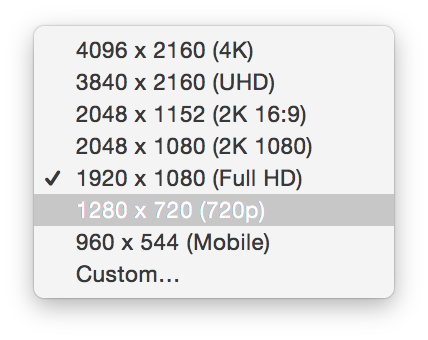
- Size (for H.264 and ProRes): This drop down menu allows you to select the final resolution of the transcoded clips:
![Fig. 3: Available frame sizes]()
Fig. 4: Available frame sizes
![Fig. 4b: The H.264 bitrate calculator]()
Fig. 4b: The H.264 bitrate calculator
The H.264 manual bitrate options allow you to enter a specific bitrate in the textfield or provide help for a choice of quality in the “H.264 bitrate calculator” (see fig. 4b).
The bitrate calculator lets you choose the intended quality from “poor” through “good” to “best” and calculates the resulting bitrate based on the selected resolution and the intended frame rate.
- Duration (Limit to In/Out points): By enabling this option Silverstack only transcodes the part of the clip between the in and out points set in the library.
Audio
Tick the checkbox to include audio in your transcoded clips.
- Format:
- Linear PCM
- ACC – Good Quality *
- ACC – High Quality *
- Channel Layout:
- All Tracks: All available audio tracks (separate tracks, no mute/solo/level taken into account) **
- All Tracks (Skip Muted Tracks): Transcodes all available audio tracks but includes neither muted audio tracks nor muted audio clips. **
- Stereo Mixdown: The custom audio mix created in the audio panel
Source
Choose different decoding options for the source formats:
- ARRIRAW:
- 1/2 resolution
- Full resolution
- SONY RAW
- 1/4 resolution
- 1/2 resolution
- Full resolution
- REDCODE RAW
- 1/8 resolution
- 1/4 resolution
- 1/2 resolution
- Full resolution
- Canon RAW
- Quality:
- Full Resolution
- 1/2 Resolution
- 1/4 Resolution
- Debayer Mode:
- AVC-Intra / XAVC
- 1/2 resolution
- Full resolution
- ProRes
- 1/4 resolution
- 1/2 resolution
- Full resolution
- Panasonic V-RAW
- Soft (GPU)
- Default (GPU)
- AHD (CPU)
- Phantom Cine
- Soft (GPU)
- Default (GPU)
- AHD (CPU)
- Cinema DNG
- Soft (GPU)
- Default (GPU)
- AHD (CPU)
- Blackmagic RAW
- 1/8 resolution
- 1/4 resolution
- 1/2 resolution
- Full resolution
Compositing
- Resizing:
- Fitting Strategy:
- The zoom to fit (Adding black bars/Without black bars) option will adjust the horizontal resolution of the clip to fit in the selected final size.
- Zoom to fill will affect the vertical resolution of the footage to the final size, cropping the sides.
- 1 to 1 will zoom the footage to 100% in the center of the image to adjust to the final selected size, cropping everything else.
![figure 6]()
figure 5: resizing example results
- Grading:
- Look Source: Choose how to manage the color data for the clip:
- As set in Library: enable this setting to include the looks applied to the clip in the Library. For more information on how to apply looks, please check the article The Silverstack Look Library.
- None: Disables the color processing and transcodes the clips unmodified (as recorded).
- From file: Reads the clip metadata and applies the color processing described in the embedded looks. In case there is no look embedded, Silverstack applies the default Log to Rec.709 conversion for the specific format.
- Frame lines: You can enter a custom aspect ratio to apply it as frame lines to the transcoded clips. Additionally, choose from different appearances in the “Appearance” dropdown.
![]()
fig. 5b: Enter a custom aspect ratio in the combo box
All entered aspect ratios will be saved in the dropdown and sorted in alphabetical order:
![fig 5b: The list of custom aspect ratios]()
fig 5b: The list of custom aspect ratios
Comments to the aspect ratios can be added in brackets after the aspect ratio (see example “2,39:1 (Cinemascope)”).
The list of aspect ratios is shared between all three places in Silverstack Lab where aspect ratios can be set: In the transcoding configurations (as explained here), in Crop, and in the Visual Controls for framing assistance.
Overlays
- Burn Ins: Choose from different options to burn in metadata in the transcoded clip:
![Fig. 6: Burn in options]()
Fig. 6: Burn in options
Note: The «Custom Text» burn in option (Silverstack Lab only) allows to add metadata wildcards into the custom text field. For instance, it’s possible to display «Scene: [scene value]-[shot value]» as shown in the following figure by writing «Scene: $scene$-$shot$» in the custom text field.
Find a list of all available keys in the article Custom Burn-In Wildcard Keys.
![]()
Fig. 6b: custom text wildcards for metadata burn ins
- Burn in Parameters: The following parameters can be adjusted for the burn ins:
- Margins: A horizontal and vertical margin to position the burn ins in the frame.
- Font: Sets the font style for the burn ins.
- Font Size: Sets the font size in pt.
- Transparency: Sets the transparency level for the burn ins.
- Text Color: Sets the text color to “White” or “Black”
- Background: Sets the background to a “Box” shape or adds an “Outline” to the text.
- Image Overlay: Choose an image overlay (.png, .jpg, .tiff) to be burned into the transcoded clips.
- Overlay parameters:
- Size: Sets the size of the image (0 -100 %)
- Position X: Sets the position in horizontal direction
- Position Y: Sets the position in vertical direction
- Transparency: Sets the transparence (0 – 100 %)
Choose a target application to automatically export a metadata file to transfer detailed clip information to different 3rd party systems.
Choose from the following export tools and formats:
Select the destination tool and click the “Configure…” button to define the detailed settings for the metadata file export. Click the links to the tools above to learn more about the configuration of the metadata exports.
The Transcoding Preview
When the transcoding tab in the right bar is showing Silverstack automatically switches to a transcoding preview to be shown in the playback view:
![Fig. 6: The transcoding preview]()
Fig. 7: The transcoding preview
The transcoding preview displays a preview of the transcoding configurations applied to the currently selected clip.
Starting a Transcoding Job
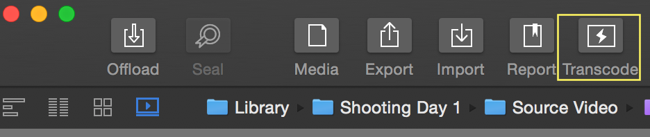
![The «Transcode» button]()
The «Transcode» button
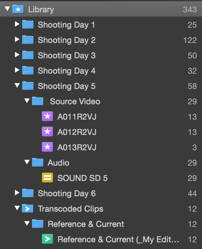
In order to start transcoding the clips, first select a folder or bin in the Library panel. Then click on Transcode to open the wizard. There you will be able to select the clips you want to transcode. Click on continue to select the destination and transcode settings.
![figure 1: clip selection wizard]()
Fig 8: clip selection wizard
Now you are able to select where the transcoded clips will be stored. You can add and remove destinations by using the «+» and «-» buttons. Alternatively, it’s also possible to modify each destination path and path wildcards. You can select from the configurations previously configured in the transcoding configurations tab:
![]()
Fig. 9: The transcoding destination step
Click the current configuration to open the list of all available transcoding configurations:
![Fig. 7: The pre-installed transcoding configurations]()
Fig. 10: The transcoding configurations dropdown
When the checkbox “Add to Library” is checked the transcoded clips will automatically be ingested into the Silverstack Lab Library after the transcoding job is done. Transcoding statistics will be available for the clips in the statistics view.
Click “Start Render Job” to start the render job. It can then be traced in the jobs panel.
Path Wildcards for Transcode Destinations
Path Wildcards can be used to customize the transcoding path with available metadata. Click the “Path wildcard” icon in the status bar (see fig. 13) to access the path wildcards settings for the selected destination:
![Fig. 11: The path wildcard window]()
Fig. 11: The path wildcard window
It is also possible to rename the transcoded clips by leaving out the “/” and optionally also adding a file extension. Here’s an example:
![Fig. 12: Path wildcards for transcoding destinations]()
Fig. 12: Path wildcards for transcoding destinations
Hint: It is also possible to copy and paste path wildcards like plain text.
Multi Destination Transcoding
Silverstack Lab is able to transcode to multiple destination formats at a time. In certain cases (see below), the transcoding of the configurations has to be run sequentially. The transcoding wizard will give you a hint if the transcoding will be run in parallel or sequentially:
![Fig. 8 : The info message about parallel or sequential transcoding]()
Fig. 13 : The info message about parallel or sequential transcoding
In case of sequential transcoding you can open the “Learn More” panel to get details about the transcoding order.
The following settings can influence the parallel execution of the transcoding job:
- In/Out Points
- Debayer settings
- Decoding resolution
Make sure to set the above settings to the same value when transcoding to two different configurations to avoid sequential transcoding.
Management of Transcoding and Offload Jobs
Silverstack Lab is generally able to transcode and copy at the same time. Transcoding jobs as well as copy jobs run in the background while the app is still fully accessible.
Optionally you can choose to pause transcoding jobs when offloading and while playing back clips. To do so go to the “Copy&Jobs” tab in the Preferences and select the according checkbox “Automatically Interrupt Transcoding Jobs during Playback and Offload”:
![Fig. 14: The "Copy&Jobs" tab in the preferences]()
Fig. 14: The “Copy&Jobs” tab in the preferences
Selection of Preferred GPU and eGPU Support
In the preferences tab “Copy&Jobs” inside the “Transcoding” section you can select the preferred GPU for transcoding. Silverstack Lab automatically shows all available GPUs in the dropdown and lets you select the preferred one for transcoding:
![Fig. 15: Select the preferred GPU in the preferences]()
Fig. 15: Select the preferred GPU in the preferences
Silverstack Lab also supports eGPUs (external GPUs) that can be attached to the machine the application is running on. Properly attached and installed eGPUs will show in the dropdown and can then be selected as the preferred GPU.
eGPUs can provide speed advantages for formats that require a lot of GPU work. Please be aware that while some transcoding tasks could be faster using an eGPU, other tasks/formats could suffer in speed. This heavily depends on source formats and transcoding configurations.
Transcoding Functionalities Overview for Silverstack Lab
- Multi Destination Transcoding
- Many custom transcoding preset
- All available burn in options
- Watermarking
- Transcoding resolutions higher than Full HD (1920 x 1080)
- Transcoding statistics
- Separate audio channels in transcoded clip
- Transcoding to DNx codecs (MXF, OP-Atom)
- Use of second GPU for transcoding
- Frame lines burn-in for transcoded clips
- Automatic metadata companion file export
*Only available for ProRes and H.264
** Not available for AAC audio codecs
Keywords: dnx36, transcoding, dnx
The post Transcoding in Silverstack Lab (Beta Version Silverstack 6.5) appeared first on Pomfort Knowledge Base.